FIND A TRUSPEED DEALER
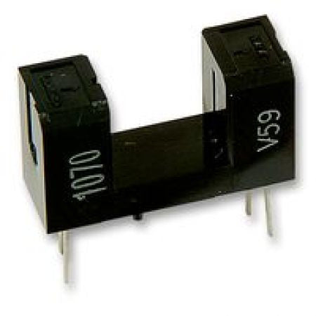
Slotted Infrared Optical switch transistor. 8mm Gap
Related product: Track Sensor Interface
Fits under the track along the slot in the track and is activated as the slot car guide passes through it.
This version has an 8mm gap for slot clearance on moulded plastic tracks.
No lighting needed, not gantry needed, no fiddly sensor alignment to worry about.
This slotted, optically coupled, Infrared transistor is ideal for a slot car lap counting and timing systems where no ambient or gantry lights are available. Conditions such as night racing are an example.
- Used with the Track Sensor Interface
- Slot gap 8mm
- Device height 10mm
- No light is needed since it has an integral transmitter and receiver co-axially aligned in the device
- U shaped slotted Sensor to mount under the track in line with the track slot for each lane
- No alignment needed since the device is moulded to maintain exact transmitter and receiver co-axis
- The U shape is 8mm wide so wont snag any slot cars and gives a reliable switching action each time a slot car guide breaks the beam between the transmitter and receiver in either side of the slotted device.
- Choose the appropriate pulse conditions for your software and interface.(Positive or Negative going pulses)
- Wire the sensors to the Track Lap Counter unit as per the diagrams in 1 & 2 Below. The additional images show the pin numbers as shown in the circuit diagrams.
- Apply power to the Track Counter unit and check that the system is working by simulating the passage of a guide through the Sensor slot.
- Choose the start/finish line on the track and mark it with a line underneath the track across the lanes.
- Cut a round or square shape hole under the lane slots big enough to just house the Slotted Sensor.
- Mount the sensor in place so that the slot in the device continues the section of track slot you cut away.
- Secure the sensor with glue or suitable putty.


