Customer Reviews
- Positive Track Wiring only.
- 5A drive with 12A Peak drive.
- Comes with 1m of cable fitted.
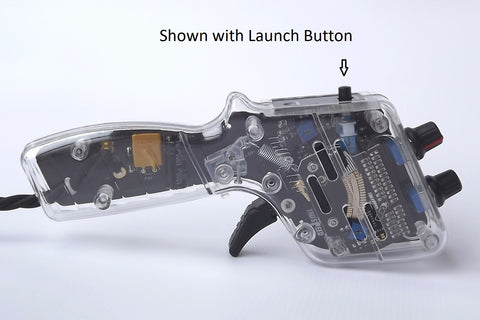
- Optional launch button.
- Not supplied with a plug.
- Optional Launch Button. (Choose from the drop down list)
- To add a UK club racing plug click here
Simple intuitive controls on the MT I make it easy to use and quick to adapt to your racing style, car, and track conditions.
Pulse Width Modulation (PWM) drive controller with unique Transistor braking.
(Review in Issue 4 of slotmagazine.co.uk)
Features:
- Scroll down for Wiring information under the Technical Tab
- Supplied with POSITIVE track wiring.
- PWM Drive with Transistor Braking.
- Brake adjustment (with automatic HOLD)
- Sensitivity adjustment. (with automatic CURVE)
- LAUNCH Switch for live start advantage. (Optional)
- Trigger return spring tension adjustment.
- Current rating of 12A peak and handling 5A constant.
- User-Changeable Single and Double Finger Trigger
- Now with 36 step wiper element and 9 point contact.
- Auto reset PTC fuse for over-current protection.
- LED with triple function.
- Not supplied with a plug. A UK standard plug is available. click here
For wiring details click here
Trigger Loop Wire instructions for earlier versions click here
Speed Control:
This is an FET PWM system. As the trigger is pulled, the PWM pulses to the car progressively widen to increase the speed of the motor.
Brake control:
(Turn Clockwise to increase Braking)
This is a Transistorised DC brake system.
A single rotary control sets the braking strength and has a built-in hold circuit to release the brakes once the car has slowed to a speed relative to the amount of brake you have selected. The useful feature of this unique design is that the motor drives the brake circuit in such a way that the faster the car is going, the harder the brakes are applied. As the car slows, the brakes are proportionally released to give very balanced and predictable control. The brake and hold remain balanced to leave you free to race confidently.
The braking action is strong at the maximum setting, but short circuit brakes are not available on this model.
Sensitivity control:
(Turn Clockwise to increase Sensitivity)
This adjusts the trigger wiper sensitivity to enable you to set the controller feel for any car or track condition. There is a built-in CURVE control circuit (similar to the PWM controller) which works automatically together with the sensitivity adjustment to give quick and easy settings. As the Sensitivity is turned up, so the initial start speed also rises slightly to match.
The little blue pre-set adjustment on the right hand side of the wiper element provides an adjustment for the range of the MODE function set on the contact board via the solder bridges.
For details on this see Contact Board 10.
KILL/ LAUNCH Switch:
-
While pressed IN, this switch cuts the feed to the car and motor, even if the trigger is pulled. Once released the power feeds in at whatever point the trigger has been pulled to. The idea is that your trigger is already pulled in so that all you need to do is release the switch to give you a quicker start from the line at the beginning of the race.
- Another useful feature of the Launch Switch is that it will act as a coasting brake when pressed. If you have a section of track that doesn't really need as much braking as you have set, then you can press the switch to allow the car to coast under its own braking.
Power LED:
- Illuminates to show that power is fed to the controller.
- Extinguishes when full power is delivered to the car.
- Goes very dim if the trigger is pressed while no car is on the track, or if the car is on the track but the braids etc. have a problem.
Wiring Colours:
- BROWN (WHITE) Power in. (Positive from Power Supply)
- BLUE (BLACK) Output. (Power from the controller to the track)
- GREEN (RED) Brake. (Negative from Power Supply)
Trigger return spring tension adjustment:
- Under the Trigger is the adjustment Screw. It operates against a cam arm that pulls the return spring. Turn clockwise to increase tension and anti-clockwise to reduce it. (you can see it work through the clear handle)
Power and Current Ratings:
-
The Mosfet PWM drive will handle motor stall currents of about 8 amperes. (This is the high current used when the slot car is stationary and builds up to high speed in a short space of time.)
- The heat sink bracket and component ratings will allow an average of 3A thereafter for general racing. There is a small heat sink to take away the slight heat build-up on the drive devices.
- There is an auto re-setting fuse in the power feed to the drive Mosfet that will cut the power if the average current use is too high for too long a period.
Maintenance
- Once you feel a scratchy operation or can hear squeaking then it is advisable to apply a small amount of the lighter fluid, or something similar, onto a cotton bud and through the air flow slots in the casing, gently wipe over the contacts on the board.
- Be sure not to bend the cable at the exit of the handle. The wiring will break from metal fatigue after a while and cause intermittent operation. Wind the cable into a gentle coil and it will last.
- Drive Mosfet TO220 P-Channel click here
- Brake Transistor TO220 NPN click here
- Sensitivity and Brake Pot B10K click here
Choose the value and style to match your model. - Replacement Cable click here
Choose length required - Trigger Sections click here
Choose full kit or plastic parts


